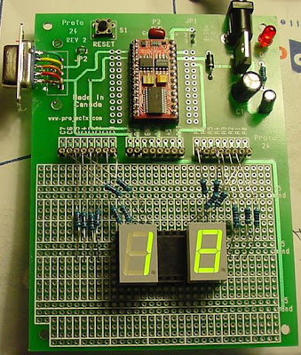
This requires two seven segment common anode displays and 16 x 470 ohm resistors.
Connections to the LA-6460 - Looking Down at the display from Above.
G F + A B
.___.
!___!
!___!
E D + C DP
It is wired up so that D0 goes to A, D1 goes to B, D2 goes to Dp, D3 goes to C, etc. Each segment connection is made with a 470 ohm resistor. The + goes to 5 volts to power up the display.
The first problem is to output the 8 bits to the I/O pins to light up the LED segments. For this we use the lookup command to find and then output a set of binary bits that set a 1 or 0 to each associated bit or segment position. A 0 will light up a segment a 1 will leave it unlit. However this outputs bit 7 first, on the left, and bit 0 last, on the right. So the 1's and 0's have to be encoded in the reverse of their segment order.
The 'OUT' command reverses the order so the segments order in software is;
F G E D C Dp B A - Segment order.
It could also be that I have them wired backwards?
Bit Segment
7 - F
6 - G
5 - E
4 - D
3 - C
2 - Dp
1 - B
0 - A
See it working on YouTube;
http://www.youtube.com/watch?v=Ouc4odEDCVA
Here is the code to make it all work. Note that percent, zero, zero is missing from some of the lines of code. Somehow blogger takes it out every time.
--------------------------------------
' {$STAMP BS2e}
delay CON 1000
upnum VAR Nib
lownum VAR Nib
DIRH = %11111111
DIRL = %11111111
n0 CON %01000100
n1 CON %11110101
n2 CON %10001100
n3 CON %10100100
n4 CON 110101
n5 CON 100110
n6 CON 000110
n7 CON %11110100
n8 CON 000100
n9 CON 100100

DO
FOR upnum = 0 TO 9
LOOKUP upnum, [n0,n1,n2,n3,n4,n5,n6,n7,n8,n9], OUTL
FOR lownum = 0 TO 9
LOOKUP lownum, [n0,n1,n2,n3,n4,n5,n6,n7,n8,n9], OUTH
PAUSE delay
NEXT
NEXT
LOOP
END
No comments:
Post a Comment