Wednesday, November 6, 2013

Remote selection relay design

We recently had an application where we needed to remotely switch between two RF amplifiers.  I used Google and searched to find a solution to no avail.  So I am posting this to save the next person a lot of time.

All we had available was the single transmission line coming from the RF amplifier.  We were sending DC up the transmission line to power the amplifier.  Because of a lightning issue we could not use anything “solid state” to create a working solution.  The first thing that comes to mind is reversing the 12 VDC to switch amplifiers, but then the amplifiers negative input was fastened to ground so that cannot be done. 

However there are some solutions to switching between the two amplifiers by pulsing the power to the remote amplifier.  All we can do is interrupt the power for a fraction of a second to switch between the amplifiers.

One solution is to use an “alternating” “impulse” or “bistable” relay.  The most common such relay is the S89R11DAC1-12. It is available from all major vendors.   The biggest problem with that relay is that it draws half an amp of power.   That might be solved by putting a capacitor between the power source and the relay so that the relay is only activated for a few seconds when the power is turned on or when it is turned off then back on.  It is also a rather large relay and it is not socketed for easy replacement.  Here is a picture of what that relay looks like.

Solution number two is to use what is called a magnetic latching relay.  These relays have two coils, one to turn it on and one to turn it off.  A capacitor in series with the relay creates a pulse that either turns the relay on or turns the relay off depending on what coil is selected.  There are several kinds of these magnetic latching relays that are available.  Model number 755XBXCD-12D has a round base and 785XBXCD-12D has a square base.  Here is a possible, untested, schematic.

The next solution is to use a conventional relay but use a capacitor to detect how long the power was off.  If the power has been off for a long time then the capacitor will be discharged.  When power comes back on the capacitor is a “short” thus delivering 12 volts to the relay.  If the power was only off for less than a second, then the capacitor is still charged and the relay only gets about three volts.  That is not enough voltage to turn the relay on.  The 12 volt relay I tested had a 150 ohm coil and required 9 volts to turn on, but it will stay on all the way down to three volts.  Hence the relay will be turned on or off depending on how long the power was off.  Here is the schematic; it was tested to work with a power supply of 9 volts all the way up to 16 volts:


Friday, November 1, 2013

A brief history of health insurance - why obamacare is a failure

A brief history of health insurance – or why some of us knew that obamacare would be a flop.

**This is my personal opinion and is full of sarcasm, it is not meant to be entirely accurate**

Many years ago, most people did not have insurance.  However, back then there were lots of “nonprofit” hospitals that would gladly take anyone without insurance.  When my first two children were born we paid the hospital $100 a month for 10 months to cover all of the expenses.  The money went directly to the hospital or doctors, there were no middlemen.  Eventually those “nonprofit” hospitals were bought out and bulldozed.  Hospitals are now in the business of making money.

Then after that change, there was what is called “Major medical” insurance.  It cost our employer about $1000 a year and it covered everything medical that totaled over $2000.  We kept all of the paperwork ourselves and then submitted it at the end of the year.  Our insurance company then sent us a check for everything that totaled over $2000.  We then used that money to cover the medical expenses for the next year. 

Then disaster struck.  Our wonderful government thought that it would fix the “problems” with health insurance.  They passed laws that invented what is called an “HMO”.  HMO insurance included “Free” physicals and many other “free” things because, as we all well know, if you see the doctor for free you will not get sick and hence you will save a lot of money.  HMO’s also required that the primary care doctor would do all of the paperwork so he had to hire two or three secretaries just to process all of that paperwork.  HMO’s would save money because the doctor would detect problems earlier and you would not get as sick.  OK, maybe the premiums would go up a little because someone had to pay for all of the secretaries to process the paperwork and someone had to pay for all of those “free” physicals, etc.  Insurance went from $1000 a year to $10,000 a year.  Thanks to the US government for figuring out how to save us money.  As a result many people were no longer insured.

Then along comes more help from the “experts” on saving money.   Yes ObamaScare to the rescue!  His idea was that if those who were well paid a little [lot] more they could cover the expenses of those who were sick.  He also eliminated being refused insurance because of “preexisting” conditions.  He also included coverage for a lot of things like abortions and sex changes.  Of course someone has to pay for all of those new extra benefits.  On top of that, if you had insurance that did not include all of the new extra benefits, it has to be cancelled.  So as a result about 1/2 to 3/4 of those with insurance will find that their insurance is now cancelled.  However they will not be able to afford the increased premiums, to pay for those that are already sick, so in the end as much as 1/2 or more of the population will be left without any health insurance.

On top of that there is the now delayed “Employer Mandate”.  Any company with more than a few employees is required to give “free” health care insurance to all of its full time employees.  The solution is simple, make them “part time” employees.  This led to massive job reductions and that led the “Employer Mandate” being delayed until after the election.    

Now if we were to go back to directly paying the doctors we could cut the cost in half because all middle men (insurance companies) do is increase the cost of seeing your doctor.  Remember ObamaScare is not medical coverage, it is health insurance, there is a huge difference there.

Common Radio Frequency Questions - RF FAQ

Radio Frequency FAQ’s
I now work for a company called ComProd Communications.  You can find us at www.comprodcom.com    We specialize in Creating RF Solutions.  There are several questions that we get asked a lot.  Here are some of the most common questions.

My antenna came with a ground plane; do I need to use it?
The ground plane is a critical part of any antenna system.  It has both a minimum size as in length and width, as well as a specific distance that it has to be from the antenna.  If you have to replace it for some reason the replacement but be larger in size as far as length and width, and it must be the exact same distance from the antenna!  The distance is critical because the reflected signal has to be in phase with the signal emitted from the antenna.  Changing the distance will cause canceling of the output of the antenna.  Making it smaller will affect the impedance of the antenna as the amount of reflected signal will vary over the length of the antenna.

Why has the cost of Combiners gone up while the cost of transmitters and receivers has gone down?
As transmitters and receivers have gotten cheaper their sensitivity and selectivity has gone down.  If the combiner does not remove unwanted frequencies then the receivers will be overloaded in their front end.  Let’s say we have a transistor RF amplifier running on 12 volts.  If it has an input signal that produces an output that is over 12 volts peak to peak it will turn it into a square wave and produce tons of harmonics.  This will totally hide the frequency that you want to receive.  The combiner must remove the unwanted frequency from both the transmitter and the receiver in order for the receiver to work correctly. 

Are antennas best stacked vertically or horizontally?
Back in the early days of audio it was common to see lots of speakers positioned horizontally across the front of the stage.  The concept was to have a speaker aimed at everyone in the audience.   At some point engineers started pointing out that if you stack the speakers one on top of the other (Vertically) you get much better sound dispersion.  Although this does not look correct to the eyes, time and experience has proven that it works.  Now most bands use vertically stacked speakers.  The same is true with antennas.  Mounting antennas one above the other seems like it would be sending signals out into space, but instead it concentrates the beam horizontally.

Why do we need separate receive and transmit antennas?
Transmitters emit some signals at unwanted frequencies, usually close to their primary broadcast frequency.  These unwanted frequencies are rapidly reduced in strength as you move away from the transmitting antenna.  However these unwanted signals can easily interfere with receivers that are operating on nearby frequencies.  If you have a separate transmit and receive antenna this problem can be drastically reduced.  Otherwise the frequency of the receiver needs to be removed from the transmitters output as well as the frequency of the transmitter must be removed from the receivers input.

Tuesday, October 29, 2013

Replacing the stove vent hood

Replacing the stove vent hood should be an easy thing to do.  However I wanted it to vent inside in the winter and then vent outside in the summer.  I also had to adapt from the new exhaust size of 7 inches to the old pipe size of 5 inches.  I used a 7 inch to 6 inch adapter, then a 6 inch to 5 inch adapter.  Then to shut off the external vent during the winter I added a 6 inch flapper.  I had to cut off the old 5 inch pipe to make room for the new adapters.  Then I had to cut 1 inch slots in the old 5 inch pipe to get the new adapter to fit inside of it.

I also had to cut bigger holes in the cupboard to fit the new 7 inch diameter pipe adapter.  Then I had to cut it two more times to make room for everything to fit together.

Then I had to assemble the adapters with the closer/flapper and test it all out prior to installation.

This is what it looked like once assembled in the cupboard.  The hole in the top of the cupboard is now closed off with duct tape.  Cutting a piece of thin plywood to fit using a cardboard model would have looked better.

I forgot a picture of what it all looks like once assembled, hopefully I will include that soon.

Dodge Stratus Fan speed control

My wife's Dodge Stratus developed a second heat control problem.  The heater fan only worked on high.  This has happened to me before on other vehicles but I could not locate the speed control assembly.  Someone told me to check under the passengers side dash near the blower motor.  It is almost impossible to see it there, without a mirror, but I was able to get a picture of it.  First remove the flimsy nut that holds on the cover, then remove the cover, and then it is visible.  Remove the two mounting screws and turn it around so you can see the back side to disconnect the electrical wires.  It requires releasing two catches to be disconnected.

The fan speed control is the light gray thing on the lower right side of this picture.


Sunday, September 15, 2013

Ford Windstar Heat Control Actuator problem

The heat stopped working in my van this spring.  That was not a serious problem for most of the summer.  Fall is here and naturally I had to fix it.  The symptom is a "clunking" noise from behind the radio/climate control.  So I removed the radio/climate control assembly by removing the two screws above the ash tray/cup holder.  I had already broken off the other two screws that were at the top of the radio/heat control section when I replaced the radio.  Way back behind everything was a white box where the noise was coming from.  I started removing the box and I dropped my nut driver down inside there somewhere.  Next I removed the two screws on each side of the bottom assembly that has the tilt out CD holder, and removed it.  Then I retrieved my nut driver and went back to work.

Here is a picture of the top of the heat control door opener as is seen behind the radio.  There are two screws to remove.
Next there is another two screws to remove at the bottom behind the climate control section.

Now if you are lucky you can remove the motor actuator and if you are like me you can take it apart to see why it makes that noise.  The smaller black gear is missing several teeth.
A replacement motorized heater door opener is $28 on eBay or about $10 more at auto parts stores. It is officially called the "Heating and AC Vent Door Actuator".  You can also replace it with a piece of copper wire to hold the door open, but that does not hold up and if you do it I guarantee it will be 90 degrees outside the next day and you will be stuck for 30 minutes in traffic on I-90.  I speak from experience!

Tuesday, August 20, 2013

DDS Function Signal Generator Sine Square Sawtooth Triangle

I recently purchased a function/signal generator on eBay.  I bought it because my computer based signal generator was limited to a top frequency of only 20KHz and I wanted to go a little higher.  I also wanted a signal generator for my "Fringe Electronic Devices" book.  I wanted to write about the signal generator for people who do not have, or do not know how to use, a computer based frequency generator.  I was delighted that this signal generator works great, and that the very limited instructions do in fact cover what is needed to get it to work.


I added spacers under the bottom two corners of the LCD to hold it in place and hot melt glued the function generator into a 3.25 inch by 4.25 inch project box.  I had to trim the bottom edge of the project box as the circuit board was just a little bit too big to fit otherwise.  A box that was 4 inches by 3.25 inches would have been a better fit.

The function generator will run on a 9V AC adapter or on a 9 volt battery with no problems.  What the signal generator is equivalent to is an Arduino with a resistor ladder based analog to digital converter.  Then there is an Op amp buffer amplifier to drive the output jacks.  I was able to find a schematic of an earlier version of the device.

My function generator did not come with a back-lit LCD so I swapped another one in.  It is a standard 1602 LCD display.  At first it did not work at all!  The first problem is a 50 ohm resistor above the LCD jack that needs to be soldered in for the back-light.  The second problem is that the LCD contrast trimmer is located underneath the LCD.  You have to play with it to get the right setting.  I was tempted to unsolder the trimmers single pin, bend it up on the other two pins and solder a jumper from the single pin to the circuit board.  That way you could adjust the trimmer while watching the LCD to see if it is the best setting.

Here is what comes with the function generator, I fixed up the English to make it more readable.

Specifications:
• Operating voltage: DC9-12V
• DDS frequency range: 1HZ-65534Hz.
• High-speed frequency (HS) output up to 8MHz;
• DDS signal amplitude and the offset amount can be adjusted separately by two potentiometers.
• DDS signals: sine wave, square wave, sawtooth, reverse sawtooth, triangle wave, ECG wave.
• 1602 LCD menu.
• Intuitive keyboard.
• Section rate steps: 1,10,100,1000,10000 Hz.
(How fast it steps when you push the right and left frequency up/down buttons)
• The power automatically restores the settings that were used the last time.
• Offset range: 0.5V pp to 5V pp
• Amplitude amount: 0.5V pp to 14V pp

Key Functions:
The UP button selects the waveform
The DOWN button selects the waveform
The LEFT button decreases the frequency
The RIGHT button increases the frequency
The START / STOP button turns the output waveform on and off

(In the off state, the "left "and "right" keys set the output frequency.  The middle button starts and stops the selected waveform) 

"UP" output waveform selection order:

High Speed = Use the high frequency output
Noise Random = random noise output
Freq Step = Size of steps
ECG = electrocardiogram wave
Rev Sawtooth = reverse sawtooth
SawTooth = sawtooth
Triangle = triangle wave
Square = square wave

Sine

This picture is what it looks like without the LCD.


Friday, August 16, 2013

Projectors for Africa

A few years ago I purchased a bunch of projectors and sent them over to pastors in Africa.  Recently a pastor has been asking me for some more projectors.  So I went on eBay, looked around, and bought eight of them for $160.  That is $20 per projector.  They are Epson EMP-S3's.  The catch is that they all have around 2000 hours on their lamps so they need new lamps that cost at least $50 each.  If anyone wants to donate to this cause it would be greatly appreciated. 

Epson EMP S3 Projectors
Someone suggested that I try to retrofit them with LED's instead.  Well the high intensity LED's are almost as expensive as the 170 watt lamps so the conversion would not save much.  But LED's sure would last a lot longer than 2000 hours.  There are some 10 watt LED's that put out about 1000 lumens at 12 volts.  Those LED's might just do the trick.  I have ordered some to give it a try.

Epson EMP S3 Projectors

The projectors arrived and almost all of them worked.  Two of them needed new lamps.  One would not start at all and one only sometimes started.  The lamp hours on most of them are likely bogus, they are running around 1000 lumens and that is typical of a lamp with more than 2000 hours on it.   The biggest problem I am facing is the air filters.  The projector filters are completely clogged and if you try to wash them out they disintegrate into nothing.  Someone on eBay is charging $20 for a replacement filter but you can buy several feet of filter material at WallMart for $1 and make your own replacement filters.
   
Epson EMP S3 Projector filters

Just cut the filter material to the right size, then glue it along the edges.  It is a tight fit to get it into the projectors, but if you tuck in the leading edge the filter fill fit nicely.

Wednesday, August 14, 2013

The Most Difficult QSC 1400 Amplifier Repair yet

I was tempted to call this the 1400 amplifier repair from hell.  It needed more repairs than any other amplifier that I have fixed in the past.  It started off with the usual 3K at two watt resistor being fried.  That caused one of the OP amps to have only four volts on pin eight instead of 15 volts like when it is working properly.  Simple enough, replace it.  I did not have a 3K two watt resistor so I used three 1K one watt resistors in series.

When the amplifier still did not work, I checked the 3.9 volt zener diodes, they another common part to fail.  However they were both good.  Then I noticed that the idle output of the OP amp was at three volts.  If I remove the OP amp, the positive input was still at .3 volts, that in turn would cause the OP amp to output 3 volts and that pushed the amplifier output to over 30 volts at idle.  So where was the .3 volts coming from?

First you need to know that QSC amplifiers work like no other amplifier.  The "ground" floats, the output transistors are directly mounted on the heat sink without an insulator, there is no center tap on the power transformer to be a ground.  So a ground reference is created with two matched resistors, one to +75 and one to -75 volts.  The middle of the resistors should be at zero volts.  That was where the problem was, one of the two matched resistors was open.  I had to replace both of them so they match, and I did not have 47K at one watt so I used two 100K at 1/2 watt resistors in parallel for each of the two 47K resistors.

Here is the schematic, I circled the blown parts in red.


Here is a picture of the repaired amplifier, red arrows point out the replaced parts.


Now I said this was a difficult repair, that is because there were two other repairs that I made along the way.  At some point I noticed that there was a resistor that was not properly soldered in.  When I soldered it, the amplifier went into shut down and would not power up.  The next problem turned out to be a bad connection on the heat sensor that is mounted on the heat sink.  With those two additional repairs, the amplifier was finally up and running.

Tuesday, August 13, 2013

I need your help getting to the top in Amazon books

   If you have read any of my books and liked them PLEASE go to Amazon and give it a positive review.  So far most of my books only have one review, and I need to have lots of positive reviews to get to the top in Amazon searches.  Most of my books are available in both printed and Kindle versions. THANKS!

Here are some of my books:
Arduino LED Projects: www.amazon.com/Arduino-L-E-D-Projects-ebook/dp/B00C4YY9DY/


Arduino LCD Projects: http://www.amazon.com/Arduino-LCD-Projects-Robert-Davis/dp/1490980709

Fringe Electronic 'Medical' Devices: http://www.amazon.com/Fringe-Electronic-Medical-Devices-Robert/dp/1491042494

Creation is a Fact!: www.amazon.com/Creation-Fact-Scientific-Historical-Evidence/dp/1491220597


The supposed upcoming worldwide solar tsunami predicted by Snowden

I looked on the "Truth or fiction" web site and cannot find anythig on this, so I thought I would give my opinion here.

IT IS PURELY FICTION!

Here is what our sun looks like now according to NASA;


I have been reading about this, but like the Y2K problem, and the Mayan calendar, I have issues with it. 

* First solar reversal happens every 11 years so this is nothing new or unusual.
* Second the impact of solar storms is totally unpredictable, most miss the earth.
* Third the greatest effect will be on things attached to long wires, like telephone and power lines, NOT on your computer or car. 

On the other hand the loss of our power grid would lead to the loss of gas for your car and gas for delivering food. As always have a six month supply of food and water on hand. Some say to have a years supply.

What they are talking about is  called the "Carrington" effect.  Back in like 1859 or something like that, a solar storm fried the telegraph wires.  By the way, these days our power grid has lots of protection, it takes direct lightning strikes and keeps on working....

All of these false "End of the World" things are to take your mind away from the REAL problem: We are at a far greater risk of a worldwide economic collapse brought on by the actions of our government and the bankers..... 

Sunday, August 11, 2013

Installing my first addressable alarm system

During the last two weekends I have spent some time back up at Elim installing a new alarm system.  It is the first addressable alarm system that I have ever worked with.  The alarm company wanted all new wiring so there were lots of wires to run as well.  The specs called for strobes or horn/strobes in every room, so the alarm panel needed a booster panel to run all of those alarm devices.

I have now had a hand in replacing the 110 volt systems with 24 volt systems and then replacing the 24 volt systems with an addressable system.


While I was there the wood started arriving to fix the roof of the Tab.  The moral of that story is to never put a flat room under an angled roof.  The snow falls off the angled roof and piles up on the flat roof.  Then the snow melts but the water cannot get through the drift.  Then the water leaks down into the rooms below.

Wednesday, July 31, 2013

Radio Shack Desoldering Tool

I rarely endorse things, and I do not get a penny for endorsing things when I do.

Recently I need to de-solder some transistors.  They were in a very tight space and getting a solder sucking tool on one side and a soldering iron on the other side was not a possibility.  So I looked at getting an all in one tool.  I was looking on eBay when someone nearby said that they had one for the same price at Radio Shack.  I could not believe it, but sure enough it was at the same price.  So I bought it and had the chance to use it.  Let me say I was very impressed, it worked perfectly.

Here is the same tool from another angle.  It is well worth the $15 price tag.


Saturday, July 20, 2013

Batavia NY Hamfest

Today I attended the Batavia NY Hamfest.  It is actually located at the Alexander Firemen Grounds on 98 south of Batavia.  To be honest it might have been the worse one ever.  I did sell a couple of items but then it started raining.  They opened up the pavilions to anyone so I moved to where there was a roof over my head, but I still did not sell much. 

On the bright side I bought the least amount of stuff that I have ever bought at an Hamfest.  All I bought was a hamburg!  There were some really nice oscilloscopes and even a scope meter, but I did not have a chance to buy anything before it started raining.

here is a picture of the pavilion that I moved to.
This was my setup before it started raining.  I moved everything I could into the back of the van when it started raining.


Chaffee NY Hamfest

Back on June 11 I went to the Chaffee NY Hamfest.  It was only the second time that I have been there.  I just today discovered that I have not posted about the Hamfests that I have been attending for about 2 or 3 years.  Even this post is a month late!

I thought that this radio was an amazing find.  
 Here is my spot, I mostly sold books.
 This is what it looked like, there were not a lot of people there.

Sunday, July 14, 2013

Gateway MS2274 Power Button Repair

I recently had a Gateway MS2274 laptop come in for repairs.  It was totally dead.  The hinges were in rough shape and some screws were missing.  The power cord had broken and was taped together in two spots.  I searched around and found another adapter but the laptop was still dead.  I started taking it apart and when I located where to power button plugs in I jumpered my screwdriver across it.  The laptop powered on and worked!  So I went on eBay and purchased a replacement.

To disassemble it there is a screw hidden on the backside of the screen hinge as well as two screws inside of the battery compartment. 

Here is the removed power switch, actually just the cord to it was bad.
Here is where the power switch is located.  You have to remove the piece above the keyboard as well as some screen screws to get to it.
 This is another picture of the power switch, it is hard to get it back together.
 Here is the screw that is hidden on the back side of the hinge. 

Monday, July 8, 2013

Arduino powered 5 Million samples per second oscope with CA3306 Part 2

It is easier for me to add another part to the previous post, than to edit that one because if I do blogger will totally trash my code.  Someone asked about the LCD display connections, etc.  First the LCD is the common 2.4 inch LCD found on eBay.  It is identified by having 18 pins at one end and two sets of pins that are perpendicular to that for the touch screen and memory card.

here is a picture of the backside of the LCD showing how the connectors are arranged.


Here is a schematic of the LCD hookup with the control pins changed so the analog ports are free.

Here is a picture of the LCD hookup for the 5 million sample per second oscilloscope.


Someone on "Hack A Day" pointed out that I left off the oscillator schematic.  Here is a schematic of the clock.  It can be any clock oscillator from 5 to 10 MC.


Thursday, June 27, 2013

Arduino powered 5 Million samples per second oscope with CA3306

This Arduino powered 5 Million samples per second oscilloscope uses an external CA3306 analog to digital converter.  the Ca3306 produces less glitches than the AD775 did.  Here is the video on YouTube. http://youtu.be/f_RD1oQuKiw   I fixed the memory issue and even sped it up some more by changing the array from 320 integers to 240 bytes.  Integers are 16 bits long and bytes are 8 bits long, so it is much faster and uses less memory. 

I also added a trigger and speed selection switch on D12 and D13 to ground.  The speed selection has 10 modes.  They range from no loop, to a loop with no delay, to eight available delay settings.

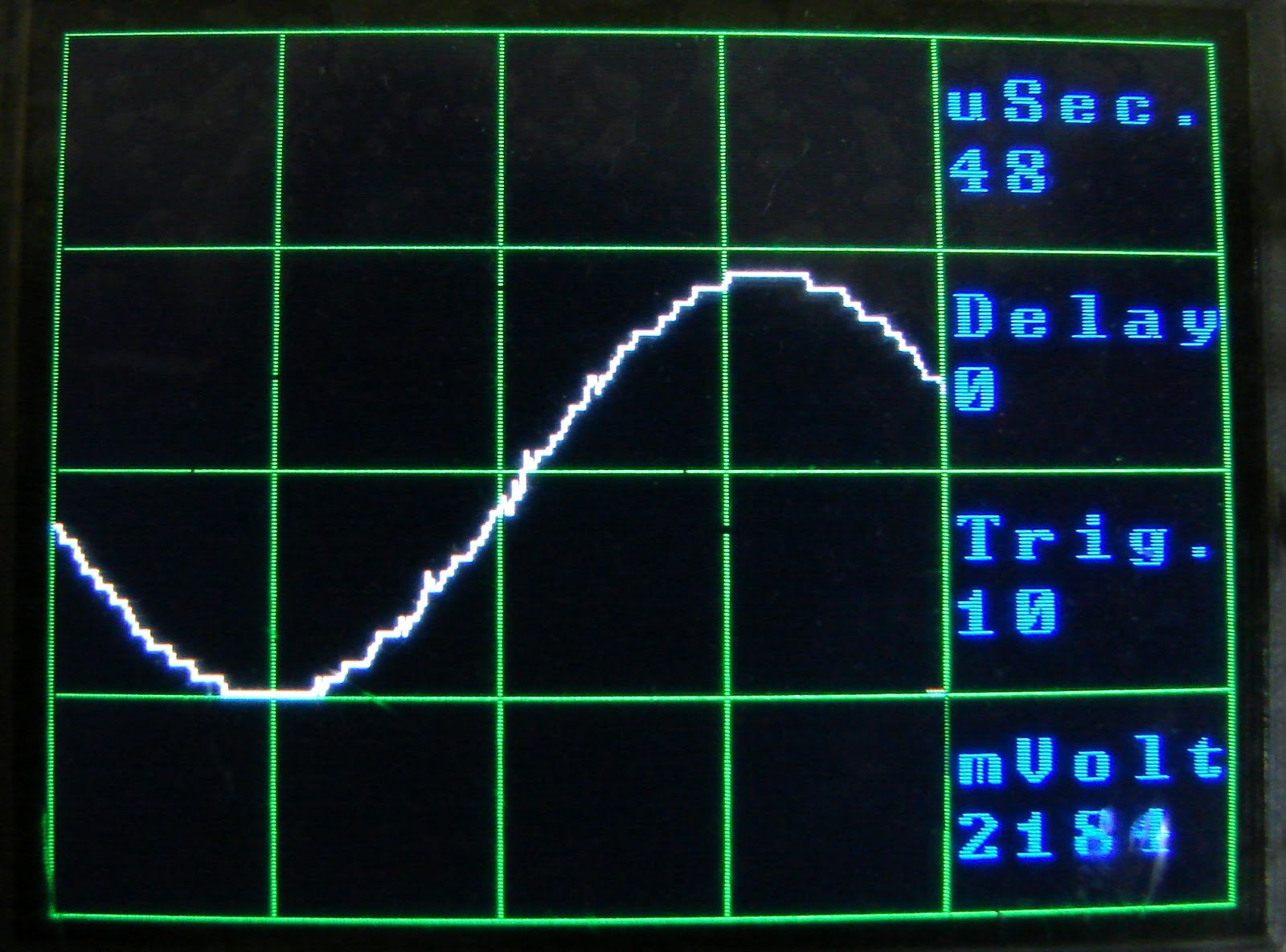
Here is a picture of the screen of the oscilloscope running in its fastest mode.


Here is a picture of the CA3306 wiring, it is much easier than the other Analog to digital converter was.


Here is the CA3306 schematic diagram;
Here is a oscilloscope like input section schematic.  I used two 9 volt batteries to test it out.  It give the ability to handle inputs of up to 50 volts and also allows gain selection. It is a much simpler design than the input section that was in my book "Digital and Computer projects".

Here is the code.  It uses two push buttons, one on D12 and one on D13 to select the sample rate and the trigger level.  To be honest the trigger does not work very well yet.
 
//****************************************
// Three color 5msps ext AtoD Scope
// By Bob Davis
// UTFT_(C)2012 Henning Karlsen
// web: http://www.henningkarlsen.com/electronics
//
// Switches on D12 & D13 determine sweep speed and trigger level
//*******************************************

#include 
// Declare which fonts we will be using
extern uint8_t SmallFont[];
extern uint8_t BigFont[];
extern uint8_t SevenSegNumFont[];

// Note that the control pins are now assigned to 8-11
UTFT myGLCD(ILI9325C,8,9,10,11);  
int Input=0;
byte Sample[320];
byte OldSample[320];
int StartSample=0;
int EndSample=0;
int MaxSample=0;
int MinSample=0;
int mode=0;
int dTime=1;
int Trigger=10;
int SampleSize=0;
int SampleTime=0;

void DrawMarkers(){
  myGLCD.setColor(0, 220, 0);
  myGLCD.drawLine(0, 0, 0, 240);
  myGLCD.drawLine(60, 0, 60, 240);
  myGLCD.drawLine(120, 0, 120, 240);
  myGLCD.drawLine(180, 0, 180, 240);
  myGLCD.drawLine(239, 0, 239, 240);
  myGLCD.drawLine(319, 0, 319, 240);
  myGLCD.drawLine(0, 0, 319, 0);
  myGLCD.drawLine(0, 60, 319, 60);
  myGLCD.drawLine(0, 120, 319, 120);
  myGLCD.drawLine(0, 180, 319, 180);
  myGLCD.drawLine(0, 239, 319, 239);
}

void setup() {
  myGLCD.InitLCD();
  myGLCD.clrScr();
  pinMode(12, INPUT);
  digitalWrite(12, HIGH);
  pinMode(13, INPUT);
  digitalWrite(13, HIGH);
  pinMode(14, INPUT);
  pinMode(15, INPUT);
  pinMode(16, INPUT);
  pinMode(17, INPUT);
  pinMode(18, INPUT);
  pinMode(19, INPUT);
}

void loop() {
// Set the background color(Red, Green, Blue) 
  myGLCD.setBackColor(0, 0, 0);
  myGLCD.setFont(BigFont);
  char buf[12]; 
  while(1) {
    DrawMarkers();
    if (digitalRead(13) == 0) mode++;
    if (mode > 10) mode=0;
// Select delay times for scan modes
    if (mode == 0) dTime=0;
    if (mode == 1) dTime=0;
    if (mode == 2) dTime=1;
    if (mode == 3) dTime=2;
    if (mode == 4) dTime=5;
    if (mode == 5) dTime=10;
    if (mode == 6) dTime=20;
    if (mode == 7) dTime=50;
    if (mode == 8) dTime=100;
    if (mode == 9) dTime=200;
    if (mode == 10) dTime=500;
// Select trigger level
    if (digitalRead(12) == 0) Trigger=Trigger+10;
    if (Trigger > 50) Trigger=0;
// Wait for input to be greater than trigger
  while (Input < Trigger){
    Input = PINC;
    }

// Collect the analog data into an array
  if (mode == 0) {
// Read analog port as a parallel port no loop
  StartSample = micros();
    Sample[0]=PINC;
    Sample[1]=PINC;     Sample[2]=PINC;    Sample[3]=PINC;    
    Sample[4]=PINC;     Sample[5]=PINC;    Sample[6]=PINC;
    Sample[7]=PINC;     Sample[8]=PINC;    Sample[9]=PINC;
    Sample[10]=PINC;    Sample[11]=PINC;    Sample[12]=PINC;
    Sample[13]=PINC;    Sample[14]=PINC;    Sample[15]=PINC;
    Sample[16]=PINC;    Sample[17]=PINC;    Sample[18]=PINC;
    Sample[19]=PINC;    Sample[20]=PINC;    Sample[21]=PINC;
    Sample[22]=PINC;    Sample[23]=PINC;    Sample[24]=PINC;
    Sample[25]=PINC;    Sample[26]=PINC;    Sample[27]=PINC;
    Sample[28]=PINC;    Sample[29]=PINC;    Sample[30]=PINC;
    Sample[31]=PINC;    Sample[32]=PINC;    Sample[33]=PINC;
    Sample[34]=PINC;    Sample[35]=PINC;    Sample[36]=PINC;
    Sample[37]=PINC;    Sample[38]=PINC;    Sample[39]=PINC;
    Sample[40]=PINC;    Sample[41]=PINC;    Sample[42]=PINC;
    Sample[43]=PINC;    Sample[44]=PINC;    Sample[45]=PINC;
    Sample[46]=PINC;    Sample[47]=PINC;    Sample[48]=PINC;
    Sample[49]=PINC;    Sample[50]=PINC;    Sample[51]=PINC;
    Sample[52]=PINC;    Sample[53]=PINC;    Sample[54]=PINC;
    Sample[55]=PINC;    Sample[56]=PINC;    Sample[57]=PINC;
    Sample[58]=PINC;    Sample[59]=PINC;    Sample[60]=PINC;
    Sample[61]=PINC;    Sample[62]=PINC;    Sample[63]=PINC;
    Sample[64]=PINC;    Sample[65]=PINC;    Sample[66]=PINC;
    Sample[67]=PINC;    Sample[68]=PINC;    Sample[69]=PINC;
    Sample[70]=PINC;    Sample[71]=PINC;    Sample[72]=PINC;
    Sample[73]=PINC;    Sample[74]=PINC;    Sample[75]=PINC;
    Sample[76]=PINC;    Sample[77]=PINC;    Sample[78]=PINC;
    Sample[79]=PINC;    Sample[80]=PINC;    Sample[81]=PINC;
    Sample[82]=PINC;    Sample[83]=PINC;    Sample[84]=PINC;
    Sample[85]=PINC;    Sample[86]=PINC;    Sample[87]=PINC;
    Sample[88]=PINC;    Sample[89]=PINC;    Sample[90]=PINC;
    Sample[91]=PINC;    Sample[92]=PINC;    Sample[93]=PINC;
    Sample[94]=PINC;    Sample[95]=PINC;    Sample[96]=PINC;
    Sample[97]=PINC;    Sample[98]=PINC;    Sample[99]=PINC;
    Sample[100]=PINC;    Sample[101]=PINC;    Sample[102]=PINC;
    Sample[103]=PINC;    Sample[104]=PINC;    Sample[105]=PINC;
    Sample[106]=PINC;    Sample[107]=PINC;    Sample[108]=PINC;
    Sample[109]=PINC;    Sample[110]=PINC;    Sample[111]=PINC;
    Sample[112]=PINC;    Sample[113]=PINC;    Sample[114]=PINC;
    Sample[115]=PINC;    Sample[116]=PINC;    Sample[117]=PINC;
    Sample[118]=PINC;    Sample[119]=PINC;    Sample[120]=PINC;
    Sample[121]=PINC;    Sample[122]=PINC;    Sample[123]=PINC;
    Sample[124]=PINC;    Sample[125]=PINC;    Sample[126]=PINC;
    Sample[127]=PINC;    Sample[128]=PINC;    Sample[129]=PINC;
    Sample[130]=PINC;    Sample[131]=PINC;    Sample[132]=PINC;
    Sample[133]=PINC;    Sample[134]=PINC;    Sample[135]=PINC;
    Sample[136]=PINC;    Sample[137]=PINC;    Sample[138]=PINC;
    Sample[139]=PINC;    Sample[140]=PINC;    Sample[141]=PINC;
    Sample[142]=PINC;    Sample[143]=PINC;    Sample[144]=PINC;
    Sample[145]=PINC;    Sample[146]=PINC;    Sample[147]=PINC;
    Sample[148]=PINC;    Sample[149]=PINC;    Sample[150]=PINC;
    Sample[151]=PINC;    Sample[152]=PINC;    Sample[153]=PINC;
    Sample[154]=PINC;    Sample[155]=PINC;    Sample[156]=PINC;
    Sample[157]=PINC;    Sample[158]=PINC;    Sample[159]=PINC;
    Sample[160]=PINC;    Sample[161]=PINC;    Sample[162]=PINC;
    Sample[163]=PINC;    Sample[164]=PINC;    Sample[165]=PINC;
    Sample[166]=PINC;    Sample[167]=PINC;    Sample[168]=PINC;
    Sample[169]=PINC;    Sample[170]=PINC;    Sample[171]=PINC;
    Sample[172]=PINC;    Sample[173]=PINC;    Sample[174]=PINC;
    Sample[175]=PINC;    Sample[176]=PINC;    Sample[177]=PINC;
    Sample[178]=PINC;    Sample[179]=PINC;    Sample[180]=PINC;
    Sample[181]=PINC;    Sample[182]=PINC;    Sample[183]=PINC;
    Sample[184]=PINC;    Sample[185]=PINC;    Sample[186]=PINC;
    Sample[187]=PINC;    Sample[188]=PINC;    Sample[189]=PINC;
    Sample[190]=PINC;    Sample[191]=PINC;    Sample[192]=PINC;
    Sample[193]=PINC;    Sample[194]=PINC;    Sample[195]=PINC;
    Sample[196]=PINC;    Sample[197]=PINC;    Sample[198]=PINC;
    Sample[199]=PINC;    Sample[200]=PINC;    Sample[201]=PINC;
    Sample[202]=PINC;    Sample[203]=PINC;    Sample[204]=PINC;
    Sample[205]=PINC;    Sample[206]=PINC;    Sample[207]=PINC;
    Sample[208]=PINC;    Sample[209]=PINC;    Sample[210]=PINC;
    Sample[211]=PINC;    Sample[212]=PINC;    Sample[213]=PINC;
    Sample[214]=PINC;    Sample[215]=PINC;    Sample[216]=PINC;
    Sample[217]=PINC;    Sample[218]=PINC;    Sample[219]=PINC;    
    Sample[220]=PINC;    Sample[221]=PINC;    Sample[222]=PINC;
    Sample[223]=PINC;    Sample[224]=PINC;    Sample[225]=PINC;
    Sample[226]=PINC;    Sample[227]=PINC;    Sample[228]=PINC;
    Sample[229]=PINC;    Sample[230]=PINC;    Sample[231]=PINC;
    Sample[232]=PINC;    Sample[233]=PINC;    Sample[234]=PINC;
    Sample[235]=PINC;    Sample[236]=PINC;    Sample[237]=PINC;
    Sample[238]=PINC;    Sample[239]=PINC;    Sample[240]=PINC;
  EndSample = micros();
  }
  if (mode == 1) {
// Read analog port as a parallel port no delay
  StartSample = micros();
  for(int xpos=0; xpos<240; xpos++) {
    Sample[xpos]=PINC;
  } 
  EndSample = micros();
  }
  if (mode >= 2) {
// Read analog port as a parallel port variable delay
  StartSample = micros();
  for(int xpos=0; xpos<240; xpos++) {
    Sample[xpos]=PINC;
    delayMicroseconds(dTime);
  } 
  EndSample = micros();
  }

// Display the collected analog data from array
  for(int xpos=0; xpos<239; xpos++) {
// Erase the old stuff
    myGLCD.setColor(0, 0, 0);
    myGLCD.drawLine (xpos+1, 255-OldSample[xpos+1]*4, xpos+2, 255-OldSample[xpos+2]*4);  
    if (xpos==0) myGLCD.drawLine (xpos+1, 1, xpos+1, 239);
// Draw the new data
    myGLCD.setColor(255, 255, 255);
    myGLCD.drawLine (xpos, 255-Sample[xpos]*4, xpos+1, 255-Sample[xpos+1]*4); 
  }  

//  Determine sample voltage peak to peak
  MaxSample = Sample[100];
  MinSample = Sample[100];
  for(int xpos=0; xpos<240; xpos++) {
    OldSample[xpos] = Sample[xpos];  
    if (Sample[xpos] > MaxSample) MaxSample=Sample[xpos];
    if (Sample[xpos] < MinSample) MinSample=Sample[xpos];
    }
// display the sample time, delay time and trigger level  
  myGLCD.setColor(0, 0, 255);
  SampleTime=EndSample-StartSample;
  myGLCD.print("uSec.", 240, 10);
  myGLCD.print("     ", 240, 30);
  myGLCD.print(itoa(SampleTime, buf, 10), 240, 30);
  myGLCD.print("Delay", 240, 70);
  myGLCD.print("     ", 240, 90);
  myGLCD.print(itoa(dTime, buf, 10), 240, 90);
  myGLCD.print("Trig.", 240, 130);
  myGLCD.print(itoa(Trigger, buf, 10), 240, 150);
// Range of 0 to 64 * 78 = 4992 mV
  SampleSize=(MaxSample-MinSample)*78;
  myGLCD.print("mVolt", 240, 190);
  myGLCD.print(itoa(SampleSize, buf, 10), 240, 210);
    } 
}


Arduino Powered 10 Million samples per second Oscilloscope

I have created an Arduino Powered 10 Million samples per second Oscilloscope. It even works at 25 Million samples per second. The secret is using an external Analog to digital converter and a FIFO. Here is the video on YouTube.http://youtu.be/RcepVnXUlJY

Here is the schematic diagram.
Here is a picture of the wiring, it is a little complicated.


There is an optional 74LS10 that prevents writes to the FIFO once it is full.  Otherwise about every 10 scans you will get a lot of garbage.

You could also add two 74LS390 dual divide by 10's and an ten position switch to have a method of selecting the recording frequency.

An op amplifier on the input would also improve the performance.  Then you could select AC/DC coupling, Gain, and divide by 10 for input options.  The position control works better with an op amp too.

Monday, June 24, 2013

Arduino 3 Million samples per second oscilloscope

I have built an Arduino powered 3 million samples per second oscilloscope. The secret to the speed is using an external Analog to Digital Converter.  Here is the video on YouTube; http://youtu.be/fG7trChbg88

This is the schematic of the AD775 Fast analog to digital converter setup;

Here is a picture of the screen.
Here is the code for 3 million samples per second, to get that fast you need to say Sample[1]=PINC a total of 320 times!
//****************************************
// Three color 3MspS ext AtoD Scope
// By Bob Davis
// UTFT_(C)2012 Henning Karlsen
// web: http://www.henningkarlsen.com/electronics
//

#include 

// Declare which fonts we will be using
extern uint8_t SmallFont[];
extern uint8_t BigFont[];
extern uint8_t SevenSegNumFont[];

// Note that control pins are now assigned to 8-11
UTFT myGLCD(ILI9325C,8,9,10,11);  
int Input=0;
int Sample[320];
int StartSTime=0;
int EndSTime=0;
float SampleTime=0;

void DrawMarkers(){
  myGLCD.setColor(0, 200, 0);
  myGLCD.drawLine(0, 0, 0, 240);
  myGLCD.drawLine(54, 0, 54, 240);
  myGLCD.drawLine(107, 0, 107, 240);
  myGLCD.drawLine(160, 0, 160, 240);
  myGLCD.drawLine(213, 0, 213, 240);
  myGLCD.drawLine(266, 0, 266, 240);
  myGLCD.drawLine(319, 0, 319, 240);
  myGLCD.drawLine(0, 0, 319, 0);
  myGLCD.drawLine(0, 50, 319, 50);
  myGLCD.drawLine(0, 100, 319, 100);
  myGLCD.drawLine(0, 150, 319, 150);
  myGLCD.drawLine(0, 200, 319, 200);
  myGLCD.drawLine(0, 239, 319, 239);
}

void setup() {
  myGLCD.InitLCD();
  myGLCD.clrScr();
  pinMode(14, INPUT);
  pinMode(15, INPUT);
  pinMode(16, INPUT);
  pinMode(17, INPUT);
  pinMode(18, INPUT);
  pinMode(19, INPUT);
}

void loop() {
  // set color(Red, Green, Blue) range = 0 to 255
  myGLCD.setBackColor(0, 0, 0);
  myGLCD.setFont(BigFont);
  char buf[12]; 
  while(1) {
    DrawMarkers(); 
// wait for trigger of a positive input
  while (Input == 0){
    Input = digitalRead(A1);
    }

// collect the analog data into an array
// Read analog port as a parallel port using PINC
// Code with no loop is about 50% faster!
  StartSTime = micros();
    Sample[0]=PINC;
    Sample[1]=PINC;     Sample[2]=PINC;    Sample[3]=PINC;    
    Sample[4]=PINC;     Sample[5]=PINC;    Sample[6]=PINC;
    Sample[7]=PINC;     Sample[8]=PINC;    Sample[9]=PINC;
    Sample[10]=PINC;    Sample[11]=PINC;    Sample[12]=PINC;
    Sample[13]=PINC;    Sample[14]=PINC;    Sample[15]=PINC;
    Sample[16]=PINC;    Sample[17]=PINC;    Sample[18]=PINC;
    Sample[19]=PINC;    Sample[20]=PINC;    Sample[21]=PINC;
    Sample[22]=PINC;    Sample[23]=PINC;    Sample[24]=PINC;
    Sample[25]=PINC;    Sample[26]=PINC;    Sample[27]=PINC;
    Sample[28]=PINC;    Sample[29]=PINC;    Sample[30]=PINC;
    Sample[31]=PINC;    Sample[32]=PINC;    Sample[33]=PINC;
    Sample[34]=PINC;    Sample[35]=PINC;    Sample[36]=PINC;
    Sample[37]=PINC;    Sample[38]=PINC;    Sample[39]=PINC;
    Sample[40]=PINC;    Sample[41]=PINC;    Sample[42]=PINC;
    Sample[43]=PINC;    Sample[44]=PINC;    Sample[45]=PINC;
    Sample[46]=PINC;    Sample[47]=PINC;    Sample[48]=PINC;
    Sample[49]=PINC;    Sample[50]=PINC;    Sample[51]=PINC;
    Sample[52]=PINC;    Sample[53]=PINC;    Sample[54]=PINC;
    Sample[55]=PINC;    Sample[56]=PINC;    Sample[57]=PINC;
    Sample[58]=PINC;    Sample[59]=PINC;    Sample[60]=PINC;
    Sample[61]=PINC;    Sample[62]=PINC;    Sample[63]=PINC;
    Sample[64]=PINC;    Sample[65]=PINC;    Sample[66]=PINC;
    Sample[67]=PINC;    Sample[68]=PINC;    Sample[69]=PINC;
    Sample[70]=PINC;    Sample[71]=PINC;    Sample[72]=PINC;
    Sample[73]=PINC;    Sample[74]=PINC;    Sample[75]=PINC;
    Sample[76]=PINC;    Sample[77]=PINC;    Sample[78]=PINC;
    Sample[79]=PINC;    Sample[80]=PINC;    Sample[81]=PINC;
    Sample[82]=PINC;    Sample[83]=PINC;    Sample[84]=PINC;
    Sample[85]=PINC;    Sample[86]=PINC;    Sample[87]=PINC;
    Sample[88]=PINC;    Sample[89]=PINC;    Sample[90]=PINC;
    Sample[91]=PINC;    Sample[92]=PINC;    Sample[93]=PINC;
    Sample[94]=PINC;    Sample[95]=PINC;    Sample[96]=PINC;
    Sample[97]=PINC;    Sample[98]=PINC;    Sample[99]=PINC;
    Sample[100]=PINC;    Sample[101]=PINC;    Sample[102]=PINC;
    Sample[103]=PINC;    Sample[104]=PINC;    Sample[105]=PINC;
    Sample[106]=PINC;    Sample[107]=PINC;    Sample[108]=PINC;
    Sample[109]=PINC;    Sample[110]=PINC;    Sample[111]=PINC;
    Sample[112]=PINC;    Sample[113]=PINC;    Sample[114]=PINC;
    Sample[115]=PINC;    Sample[116]=PINC;    Sample[117]=PINC;
    Sample[118]=PINC;    Sample[119]=PINC;    Sample[120]=PINC;
    Sample[121]=PINC;    Sample[122]=PINC;    Sample[123]=PINC;
    Sample[124]=PINC;    Sample[125]=PINC;    Sample[126]=PINC;
    Sample[127]=PINC;    Sample[128]=PINC;    Sample[129]=PINC;
    Sample[130]=PINC;    Sample[131]=PINC;    Sample[132]=PINC;
    Sample[133]=PINC;    Sample[134]=PINC;    Sample[135]=PINC;
    Sample[136]=PINC;    Sample[137]=PINC;    Sample[138]=PINC;
    Sample[139]=PINC;    Sample[140]=PINC;    Sample[141]=PINC;
    Sample[142]=PINC;    Sample[143]=PINC;    Sample[144]=PINC;
    Sample[145]=PINC;    Sample[146]=PINC;    Sample[147]=PINC;
    Sample[148]=PINC;    Sample[149]=PINC;    Sample[150]=PINC;
    Sample[151]=PINC;    Sample[152]=PINC;    Sample[153]=PINC;
    Sample[154]=PINC;    Sample[155]=PINC;    Sample[156]=PINC;
    Sample[157]=PINC;    Sample[158]=PINC;    Sample[159]=PINC;
    Sample[160]=PINC;    Sample[161]=PINC;    Sample[162]=PINC;
    Sample[163]=PINC;    Sample[164]=PINC;    Sample[165]=PINC;
    Sample[166]=PINC;    Sample[167]=PINC;    Sample[168]=PINC;
    Sample[169]=PINC;    Sample[170]=PINC;    Sample[171]=PINC;
    Sample[172]=PINC;    Sample[173]=PINC;    Sample[174]=PINC;
    Sample[175]=PINC;    Sample[176]=PINC;    Sample[177]=PINC;
    Sample[178]=PINC;    Sample[179]=PINC;    Sample[180]=PINC;
    Sample[181]=PINC;    Sample[182]=PINC;    Sample[183]=PINC;
    Sample[184]=PINC;    Sample[185]=PINC;    Sample[186]=PINC;
    Sample[187]=PINC;    Sample[188]=PINC;    Sample[189]=PINC;
    Sample[190]=PINC;    Sample[191]=PINC;    Sample[192]=PINC;
    Sample[193]=PINC;    Sample[194]=PINC;    Sample[195]=PINC;
    Sample[196]=PINC;    Sample[197]=PINC;    Sample[198]=PINC;
    Sample[199]=PINC;    Sample[200]=PINC;    Sample[201]=PINC;
    Sample[202]=PINC;    Sample[203]=PINC;    Sample[204]=PINC;
    Sample[205]=PINC;    Sample[206]=PINC;    Sample[207]=PINC;
    Sample[208]=PINC;    Sample[209]=PINC;    Sample[210]=PINC;
    Sample[211]=PINC;    Sample[212]=PINC;    Sample[213]=PINC;
    Sample[214]=PINC;    Sample[215]=PINC;    Sample[216]=PINC;
    Sample[217]=PINC;    Sample[218]=PINC;    Sample[219]=PINC;    
    Sample[220]=PINC;    Sample[221]=PINC;    Sample[222]=PINC;
    Sample[223]=PINC;    Sample[224]=PINC;    Sample[225]=PINC;
    Sample[226]=PINC;    Sample[227]=PINC;    Sample[228]=PINC;
    Sample[229]=PINC;    Sample[230]=PINC;    Sample[231]=PINC;
    Sample[232]=PINC;    Sample[233]=PINC;    Sample[234]=PINC;
    Sample[235]=PINC;    Sample[236]=PINC;    Sample[237]=PINC;
    Sample[238]=PINC;    Sample[239]=PINC;    Sample[240]=PINC;
    Sample[241]=PINC;    Sample[242]=PINC;    Sample[243]=PINC;
    Sample[244]=PINC;    Sample[245]=PINC;    Sample[246]=PINC;
    Sample[247]=PINC;    Sample[248]=PINC;    Sample[249]=PINC;
    Sample[250]=PINC;    Sample[251]=PINC;    Sample[252]=PINC;
    Sample[253]=PINC;    Sample[254]=PINC;    Sample[255]=PINC;
    Sample[256]=PINC;    Sample[257]=PINC;    Sample[258]=PINC;
    Sample[259]=PINC;    Sample[260]=PINC;    Sample[261]=PINC;
    Sample[262]=PINC;    Sample[263]=PINC;    Sample[264]=PINC;
    Sample[265]=PINC;    Sample[266]=PINC;    Sample[267]=PINC;
    Sample[268]=PINC;    Sample[269]=PINC;    Sample[270]=PINC;
    Sample[271]=PINC;    Sample[272]=PINC;    Sample[273]=PINC;
    Sample[274]=PINC;    Sample[275]=PINC;    Sample[276]=PINC;
    Sample[277]=PINC;    Sample[278]=PINC;    Sample[279]=PINC;
    Sample[280]=PINC;    Sample[281]=PINC;    Sample[282]=PINC;
    Sample[283]=PINC;    Sample[284]=PINC;    Sample[285]=PINC;
    Sample[286]=PINC;    Sample[287]=PINC;    Sample[288]=PINC;
    Sample[289]=PINC;    Sample[290]=PINC;    Sample[291]=PINC;
    Sample[292]=PINC;    Sample[293]=PINC;    Sample[294]=PINC;
    Sample[295]=PINC;    Sample[296]=PINC;    Sample[297]=PINC;
    Sample[298]=PINC;    Sample[299]=PINC;    Sample[300]=PINC;
    Sample[301]=PINC;    Sample[302]=PINC;    Sample[303]=PINC;
    Sample[304]=PINC;    Sample[305]=PINC;    Sample[306]=PINC;
    Sample[307]=PINC;    Sample[308]=PINC;    Sample[309]=PINC;
    Sample[310]=PINC;    Sample[311]=PINC;    Sample[312]=PINC;
    Sample[313]=PINC;    Sample[314]=PINC;    Sample[315]=PINC;
    Sample[316]=PINC;    Sample[317]=PINC;    Sample[318]=PINC;
    Sample[319]=PINC;   
   EndSTime = micros();
// display the collected analog data from array
  for(int xpos=0; xpos<319; xpos++) {
    // Erase old stuff
    myGLCD.setColor(0, 0, 0);
    myGLCD.drawLine (xpos+1, 1, xpos+1, 180);
    // Draw new data
    if (xpos%10==0) DrawMarkers(); 
    myGLCD.setColor(255, 255, 255);
    myGLCD.drawLine (xpos, Sample[xpos]*2, xpos+1, Sample[xpos+1]*2);  }  
  // display the sample time  
  myGLCD.setColor(0, 0, 255);
  SampleTime = EndSTime - StartSTime;
  myGLCD.print("uSeconds=          ", 10, 220);
  myGLCD.print(ltoa(SampleTime, buf, 10), 170, 220);
    } 
}

Thursday, June 20, 2013

Universal 8 Bit Graphics Library bug

A while back I posted a video that showed a strange bug that was happening with my oscilloscope LCD program. It used U8GLib or the Universal 8 Bit Graphics Library.  The video is available at, http://youtu.be/1qPy6FVSllY

** UPDATE ** This problem is caused by updating the data while it is being displayed.  The update must not happen within the display loop.

Then I made a perfectly working oscilloscope using the Universal TFT Library and a better LCD. So then I thought I would go back and see what was the problem with U8GLib.

To rule out the LCD display I purchased a KS0108 compatible display because I could run it with its own support software or with the U8GLib.  With the KS0108 driver, I could not scale the amplitude of the input waveform, a new issue.  However the sine wave turned out perfectly using the KS0108 driver.  Then the same software really went crazy when I tried to use the U8GLib drivers.  Here is the video on YouTube, http://youtu.be/l-I4vf83OIc

Does anyone else have this problem or know of a solution??

Here is a picture of what the display should look like;


 But this is what happens when you move the position control to center the sine wave;