Tuesday, August 20, 2013

DDS Function Signal Generator Sine Square Sawtooth Triangle

I recently purchased a function/signal generator on eBay.  I bought it because my computer based signal generator was limited to a top frequency of only 20KHz and I wanted to go a little higher.  I also wanted a signal generator for my "Fringe Electronic Devices" book.  I wanted to write about the signal generator for people who do not have, or do not know how to use, a computer based frequency generator.  I was delighted that this signal generator works great, and that the very limited instructions do in fact cover what is needed to get it to work.


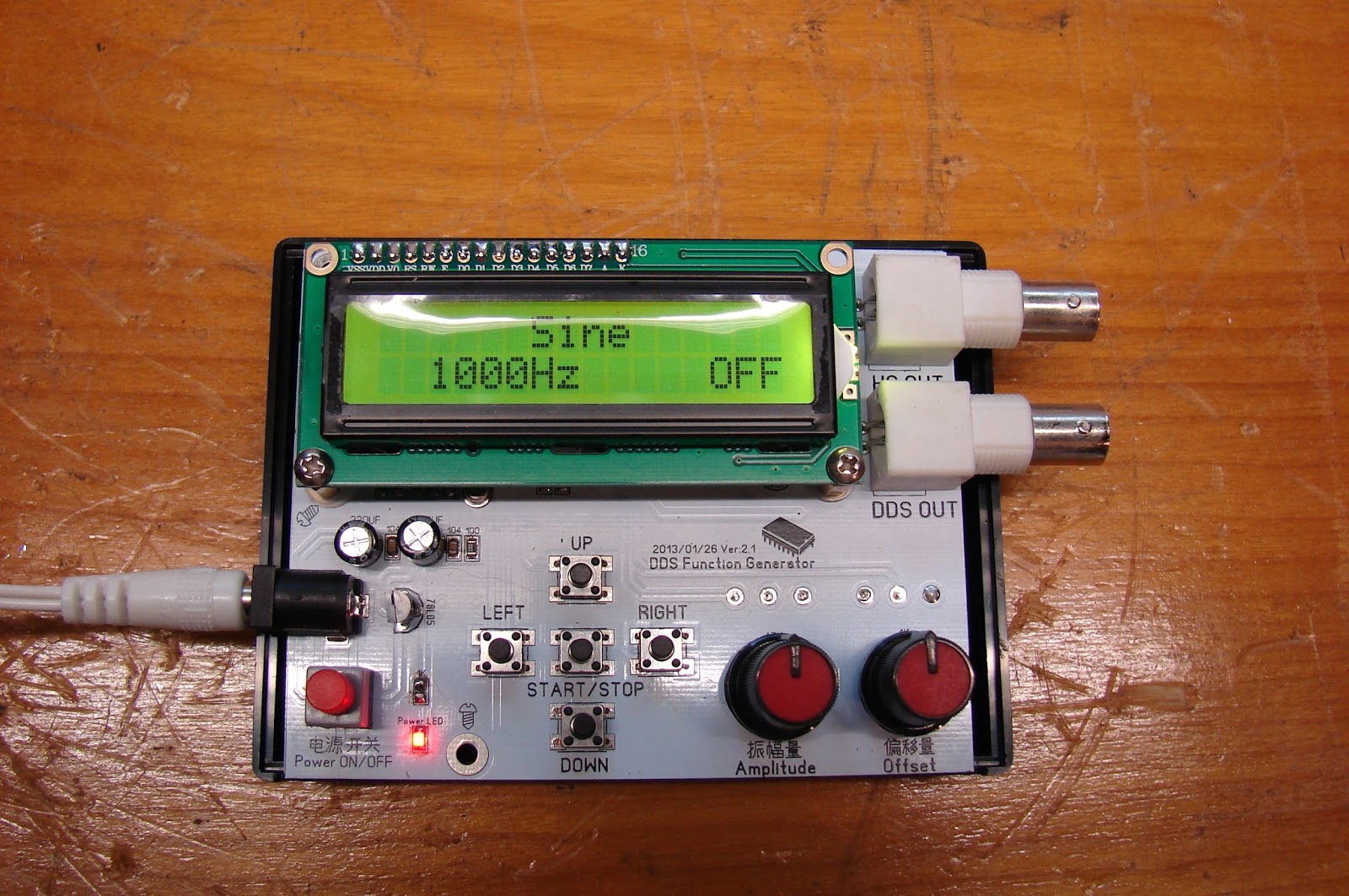
I added spacers under the bottom two corners of the LCD to hold it in place and hot melt glued the function generator into a 3.25 inch by 4.25 inch project box.  I had to trim the bottom edge of the project box as the circuit board was just a little bit too big to fit otherwise.  A box that was 4 inches by 3.25 inches would have been a better fit.

The function generator will run on a 9V AC adapter or on a 9 volt battery with no problems.  What the signal generator is equivalent to is an Arduino with a resistor ladder based analog to digital converter.  Then there is an Op amp buffer amplifier to drive the output jacks.  I was able to find a schematic of an earlier version of the device.

My function generator did not come with a back-lit LCD so I swapped another one in.  It is a standard 1602 LCD display.  At first it did not work at all!  The first problem is a 50 ohm resistor above the LCD jack that needs to be soldered in for the back-light.  The second problem is that the LCD contrast trimmer is located underneath the LCD.  You have to play with it to get the right setting.  I was tempted to unsolder the trimmers single pin, bend it up on the other two pins and solder a jumper from the single pin to the circuit board.  That way you could adjust the trimmer while watching the LCD to see if it is the best setting.

Here is what comes with the function generator, I fixed up the English to make it more readable.

Specifications:
• Operating voltage: DC9-12V
• DDS frequency range: 1HZ-65534Hz.
• High-speed frequency (HS) output up to 8MHz;
• DDS signal amplitude and the offset amount can be adjusted separately by two potentiometers.
• DDS signals: sine wave, square wave, sawtooth, reverse sawtooth, triangle wave, ECG wave.
• 1602 LCD menu.
• Intuitive keyboard.
• Section rate steps: 1,10,100,1000,10000 Hz.
(How fast it steps when you push the right and left frequency up/down buttons)
• The power automatically restores the settings that were used the last time.
• Offset range: 0.5V pp to 5V pp
• Amplitude amount: 0.5V pp to 14V pp

Key Functions:
The UP button selects the waveform
The DOWN button selects the waveform
The LEFT button decreases the frequency
The RIGHT button increases the frequency
The START / STOP button turns the output waveform on and off

(In the off state, the "left "and "right" keys set the output frequency.  The middle button starts and stops the selected waveform) 

"UP" output waveform selection order:

High Speed = Use the high frequency output
Noise Random = random noise output
Freq Step = Size of steps
ECG = electrocardiogram wave
Rev Sawtooth = reverse sawtooth
SawTooth = sawtooth
Triangle = triangle wave
Square = square wave

Sine

This picture is what it looks like without the LCD.


Friday, August 16, 2013

Projectors for Africa

A few years ago I purchased a bunch of projectors and sent them over to pastors in Africa.  Recently a pastor has been asking me for some more projectors.  So I went on eBay, looked around, and bought eight of them for $160.  That is $20 per projector.  They are Epson EMP-S3's.  The catch is that they all have around 2000 hours on their lamps so they need new lamps that cost at least $50 each.  If anyone wants to donate to this cause it would be greatly appreciated. 

Epson EMP S3 Projectors
Someone suggested that I try to retrofit them with LED's instead.  Well the high intensity LED's are almost as expensive as the 170 watt lamps so the conversion would not save much.  But LED's sure would last a lot longer than 2000 hours.  There are some 10 watt LED's that put out about 1000 lumens at 12 volts.  Those LED's might just do the trick.  I have ordered some to give it a try.

Epson EMP S3 Projectors

The projectors arrived and almost all of them worked.  Two of them needed new lamps.  One would not start at all and one only sometimes started.  The lamp hours on most of them are likely bogus, they are running around 1000 lumens and that is typical of a lamp with more than 2000 hours on it.   The biggest problem I am facing is the air filters.  The projector filters are completely clogged and if you try to wash them out they disintegrate into nothing.  Someone on eBay is charging $20 for a replacement filter but you can buy several feet of filter material at WallMart for $1 and make your own replacement filters.
   
Epson EMP S3 Projector filters

Just cut the filter material to the right size, then glue it along the edges.  It is a tight fit to get it into the projectors, but if you tuck in the leading edge the filter fill fit nicely.

Wednesday, August 14, 2013

The Most Difficult QSC 1400 Amplifier Repair yet

I was tempted to call this the 1400 amplifier repair from hell.  It needed more repairs than any other amplifier that I have fixed in the past.  It started off with the usual 3K at two watt resistor being fried.  That caused one of the OP amps to have only four volts on pin eight instead of 15 volts like when it is working properly.  Simple enough, replace it.  I did not have a 3K two watt resistor so I used three 1K one watt resistors in series.

When the amplifier still did not work, I checked the 3.9 volt zener diodes, they another common part to fail.  However they were both good.  Then I noticed that the idle output of the OP amp was at three volts.  If I remove the OP amp, the positive input was still at .3 volts, that in turn would cause the OP amp to output 3 volts and that pushed the amplifier output to over 30 volts at idle.  So where was the .3 volts coming from?

First you need to know that QSC amplifiers work like no other amplifier.  The "ground" floats, the output transistors are directly mounted on the heat sink without an insulator, there is no center tap on the power transformer to be a ground.  So a ground reference is created with two matched resistors, one to +75 and one to -75 volts.  The middle of the resistors should be at zero volts.  That was where the problem was, one of the two matched resistors was open.  I had to replace both of them so they match, and I did not have 47K at one watt so I used two 100K at 1/2 watt resistors in parallel for each of the two 47K resistors.

Here is the schematic, I circled the blown parts in red.


Here is a picture of the repaired amplifier, red arrows point out the replaced parts.


Now I said this was a difficult repair, that is because there were two other repairs that I made along the way.  At some point I noticed that there was a resistor that was not properly soldered in.  When I soldered it, the amplifier went into shut down and would not power up.  The next problem turned out to be a bad connection on the heat sensor that is mounted on the heat sink.  With those two additional repairs, the amplifier was finally up and running.

Tuesday, August 13, 2013

I need your help getting to the top in Amazon books

   If you have read any of my books and liked them PLEASE go to Amazon and give it a positive review.  So far most of my books only have one review, and I need to have lots of positive reviews to get to the top in Amazon searches.  Most of my books are available in both printed and Kindle versions. THANKS!

Here are some of my books:
Arduino LED Projects: www.amazon.com/Arduino-L-E-D-Projects-ebook/dp/B00C4YY9DY/


Arduino LCD Projects: http://www.amazon.com/Arduino-LCD-Projects-Robert-Davis/dp/1490980709

Fringe Electronic 'Medical' Devices: http://www.amazon.com/Fringe-Electronic-Medical-Devices-Robert/dp/1491042494

Creation is a Fact!: www.amazon.com/Creation-Fact-Scientific-Historical-Evidence/dp/1491220597


The supposed upcoming worldwide solar tsunami predicted by Snowden

I looked on the "Truth or fiction" web site and cannot find anythig on this, so I thought I would give my opinion here.

IT IS PURELY FICTION!

Here is what our sun looks like now according to NASA;


I have been reading about this, but like the Y2K problem, and the Mayan calendar, I have issues with it. 

* First solar reversal happens every 11 years so this is nothing new or unusual.
* Second the impact of solar storms is totally unpredictable, most miss the earth.
* Third the greatest effect will be on things attached to long wires, like telephone and power lines, NOT on your computer or car. 

On the other hand the loss of our power grid would lead to the loss of gas for your car and gas for delivering food. As always have a six month supply of food and water on hand. Some say to have a years supply.

What they are talking about is  called the "Carrington" effect.  Back in like 1859 or something like that, a solar storm fried the telegraph wires.  By the way, these days our power grid has lots of protection, it takes direct lightning strikes and keeps on working....

All of these false "End of the World" things are to take your mind away from the REAL problem: We are at a far greater risk of a worldwide economic collapse brought on by the actions of our government and the bankers..... 

Sunday, August 11, 2013

Installing my first addressable alarm system

During the last two weekends I have spent some time back up at Elim installing a new alarm system.  It is the first addressable alarm system that I have ever worked with.  The alarm company wanted all new wiring so there were lots of wires to run as well.  The specs called for strobes or horn/strobes in every room, so the alarm panel needed a booster panel to run all of those alarm devices.

I have now had a hand in replacing the 110 volt systems with 24 volt systems and then replacing the 24 volt systems with an addressable system.


While I was there the wood started arriving to fix the roof of the Tab.  The moral of that story is to never put a flat room under an angled roof.  The snow falls off the angled roof and piles up on the flat roof.  Then the snow melts but the water cannot get through the drift.  Then the water leaks down into the rooms below.