Someone gave me a 40 inch TV that they found in the garbage. It actually worked at first but after about 15 minutes the picture started jumping. The first thing I did was to replace all the capacitors in the power supply. They are located in the upper right corner of the next picture. I used 1000 uF at 16 volt caps. Be careful the polarity of one cap is the opposite of all of the others. That did not help.
I discovered that if I plug in a computer the picture jumps non stop. So I replaced the input board as shown below. This fixed the problem but introduced another problem. The new board had the V-Chip programmed to block some shows. Now I have to get a remote control so I can wipe out the memory and hence delete the V-Chip programming.
I suspect the problem is in the power supply section located in the upper left corner. The regulators have been so hot that the metal is purple in color. I think I will start by replacing the 100 uF at 25 volt caps.
Replacing the capacitors was a complete flop. I tried carefully wiggling the caps from side to side to remove them but in every case I removed the runs from the board. I guess I am staying with the new board as it mostly works. I was able to wipe out the V Chip programming with the remote control.
Over the weekend I finally got around to repairing this Ramsa Mixer. The symptoms included that the solo light was on in one place and not on at another and that the overload LED's were lit with no input. I opened it up to look inside and then everything started working correctly.
I started wiggling things and when I touched the power supply the mixer stopped working. So I removed it and examined it for bad connections. Sure enough one of the voltage regulators was no longer soldered in.
There are many robot kits on eBay. They all lack a "head". So to get ahead you need to make your own. I used a "Make your own Christmas tree Ornament". They sell these 2.5 inch diameter clear plastic balls that you can use to make Christmas tree ornaments. They can also make a head for your robot. Here is a picture of a robot without a head, just a servo motor.
He looks better with the clear ball over the servo.
You can also paint it and add a circuit board with some LED's for eyes and a mouth like in this picture.
Here is another DIY robot head this time it is made out of a 3.2 inch Christmas tree bulb.
Its time for an update on the spider robot. So far I have repaired the sensor shield twice, replaced the power cable and now replaced two of the servos. I have changed two of the MG996's to the more powerful MG958's. That made a huge difference! The spider can now get up completely off the floor! The new servos also made the spider a lot quieter as the other servos do not have to work as hard.
Here is a picture of the spider folded in.
Here is a picture of him walking.
Here is video one before replacing the two servos with MG958's.
Over the weekend I found and fixed the design bug that prevents servos from working properly when they are connected to the analog port connectors of the standard servo/sensor shield. The problem is that the logic five volts is always used to power those servos. If there is any load on the servos they will overload and shut down the logic five volt voltage regulator. The fix involves cutting two runs and adding two jumpers. This change is needed to route the five volts around the servo connectors.
The problem showed up with my spider robot project. Some servos tried to come to life without the six volt power supply being turned on. It took a while to figure out where they were getting their power from. The logic five volts was being pulled down to about two volts!
Also do not forget to remove the green jumper near the six volt power input screws. It will also short the five volt logic power into powering the servos. That could seriously damage the Arduino!
Another thing you might need to do to use more than 12 servos is to change a line in servo.h. This limit gets mistaken as to why servos do not work on the analog pins. There are usually 12 servos already on the digital pins and when you try to use the analog pins you have exceeded the 12 servo limit. The line says something like "Maximum servos per timer = 12" and you will need to change it to 18 or even 20 if you want. I have made the change months ago and it does not hurt anything to increase the maximum servos per timer. Servo.h can be found in your Arduino/libraries/servo folder.
While working on my "Spider" smoke rolled off the Servo/Sensor shield. This time a run had burned off the board! I never had these problems with my home made servo shield! Here is a picture of the burned run in the top left corner:
Here is the cure for the burnt run as well as a cure for the power distribution issues. basically you take power from the screw terminal and distribute it to the top and middle of the 16 digital pin servo connectors as well as to the top of the 6 analog pin servo connectors. With this change the spider worked perfectly.
While I am showing fried stuff, here is what happens when you buy a cheap servo on eBay:
Get real servos that say "Tower Pro" not "TowardPro". Do not buy them if the seller intentionally hides the manufacturer name. There are a lot of junk servos on eBay!
Another issue I just confirmed is that all HiTec servos work in the opposite direction of all other servos. I now have five HiTec servos! There are two options: Sell them or figure out how to reverse them internally. I might do that and then post on how to reverse them.
My next project is a six legged robot. I look at these projects that are all using an Arduino Uno and servos like they are a modern day version of the "erector set" that I played with as a kid. This is a more economical way to build these various projects instead of buying several expensive kits. Basically I am using the same parts to make all of the following projects:
5,9,13,17 DOF Humanoid robots
14 DOF Dog robot
17 DOF Dinosaur robot
18 DOF Spider robot
I have looked at several hexapod designs and so far I have been able to reproduce the body using standard parts. The other designs use two custom plates spaced about two inches apart. My design uses:
4 - Angled "U" brackets
2 - Straight "U" brackets
2 - Waist brackets
4 - Straight brackets
2 - "L" Shaped brackets.
Here is a top view of my design for the hexapod body.
This next picture is a side view of the hexapod body:
So now to collect at least 18 servos to make it work.
I decided to make my own lower legs. I used a picture from a kit on ebay and blew it up to the actual size. Then I cut it out and used it as a model. These legs were cut out with a hand held jig saw. They did not look that good in clear plastic so I painted them black.
This is after two coats of paint.
This is what they look like on the assembled spider. They are still a little rough.
Here is how I assembled the servo mounting brackets. Then I added the servos and then mounted them on the robot.
The Arduino mounted real nicely using some of the existing holes in the bracket.
Here is the completed spider as far as the mechanical assembly.
I plan on making some more creations besides the 9, 13, and 17 DOF humanoid robots from the robot kit. The next one is this 14 DOF "Dog" robot. This is actually the third revision and there will be more to come. As you can see I have had a hard time with attaching the "tail". The "Mouth" is a robot hand or it was....
He is starting to work. Here is the latest picture of him. He lost his "feet" and has a more solid rear end.
And now for his first video appearance.
The next thing to do is to add a tail and make him into a dinosaur.
Here is the dinosaur video.
He has now grown to three feet long and has LED eyes.
Here is his second video with greatly improved software.
After not having a lot of success with a more complex robot I went backwards and built a 9 DOF humanoid robot. Here is a picture of that robot.
Here is the video of him walking.
Up next is the 13 DOF humanoid robot.
Here is his video.
Here is his servo array to make him walk forward.
int walkf[6][6] = {
// 0 1
2 3 4
5
{ 80, 80,
80, 85, 90,
90}, // Left Ankle
{ 90, 80,
70, 70, 70,
80}, // Knee
{ 90, 80,
70, 70, 70,
80}, // Hip
{100, 100, 100, 95,
90, 85}, // Right Ankle
{ 90, 90,
80, 70, 70,
80}, // Knee
{ 90, 90,
80, 70, 70,
80}, // Hip
};
I still cannot get a 17 DOF robot to work very well. My servos are too weak for the weight! Do not buy the MG995 or MG945 servos except for the arms (or for a 9-13 DOF robot). I have burned some up trying to power the 17DOF robots legs. I am thinking of trying the MG958. Anyone know if that servo has enough power?
Here is some more Information that I have discovered about servos
and robots.
Be sure the servo that you buy is not a cheap
imitation. This can be detected by the
seller hiding the manufacturer name or misspelling the manufacturer name. A common example would be “Tower Pro” (real) or
“Towerd Pro” (fake).
This is my new rule of thumb for making humanoid, as in 2 legged
robots. The problem is that the more the
servos (and their connecting hardware) the more the robot weighs.
The leg servos of a 5-9 DOF Humanoid robot should handle 100
oz. inches of torque.
The leg servos of a 10-15 DOF Humanoid robot should handle 150 oz. inches of
torque.
The leg servos of a 16-20 DOF Humanoid robot should handle 200 oz. inches of
torque.
I am back to working on the walking humanoid robot after writing another book. First I had to make an Arduino Shield to control the servo's. Here is a video testing the servo shield.
Next is to connect it to the robot and get those servo's working. I am using an IR remote control to test his movements. This is a picture of the front view of the setup.
Here is the back view. The arduino has been mounted in place for this picture.
Here is a video of me testing out the robot servo's.
Here is a second video with most of the servo's working and they are now "zeroed".
In spite of the really bad servo's he is taking his first steps.
Here is a two servo per leg version of the robot.
Here is the code for the two servo per leg robot in video 4.
void StepForward(){
//Moving Left Leg Forward
servo1.write(75); //shift weight
to left ankle
servo3.write(60); //right ankle
kicks weight over
delay(200);
servo3.write(70); //free ankle
lifts
servo2.write(110);
//left hip
servo4.write(120);
//right hip
delay(200);
servo1.write(90); //level leftt
ankle
servo3.write(90); //level right
ankle
delay(200);
servo1.write(115); //Shift weight to right ankle
servo3.write(110);
delay(200);
servo1.write(110); //free ankle
lifts
servo2.write(70); //left hip
servo4.write(60); //right hip
delay(200);
servo1.write(90); //left ankle - back to home positions
I have been wrining a book of "Arduino Oscilloscope Projects". In this book I show 4 different LCD's, 5 different Analog to digital converters, and 3 different analog front ends. The code has greatly improved with a "gain" in software feature. I have written the code for a 1.8 SPI TFT screen as well as for a 2.4 inch or 2.8 inch ILI9341 Screen.
Here is what the 1.8 inch screen looks like. On the bigger screens the sample time in MS is located under the other text fields on the right side.
Here is what the assembled oscilloscope looks like so far.
This is a picture of the main board without the LCD screen.
This is the front cover. I need to wire the cover to the main board next.
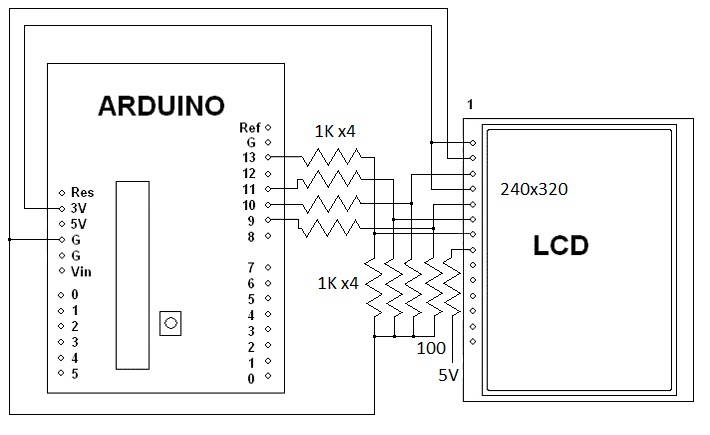
Over the weekend I figured out how to interface a 2.8 inch SPI TFT that has a ILI9341 chip to an Arduino Uno. All it takes is eight 1K resistors. Most people use a 4050 IC. Here is the schematic.
I am using the Adafruit ILI9341 driver found at: https://github.com/adafruit/Adafruit_ILI9341
Note that the Adafruit LCD has level shifters for 5 volts built into it.
Here is a video of it working on Youtube.
Here is a video of the LCD being used as an oscilloscope.
Here are a couple of still pictures, only 6 of the 8 bits are connected for these pictures.
Here is the code for a more basic oscilloscope.
/************************************
2.8 SPI PIND TFT Oscope Simple
Reads the D0-D7 pins using PIND,
and shows the value on the screen.
Created 27 july 2015 by Bob Davis
**************************************/
//#include // Arduino LCD library
#include
#include "Adafruit_ILI9341.h"
#include "Adafruit_GFX.h"
// pin definition for the Uno LCD
#define TFT_DC 9
#define TFT_CS 10
// Use hardware SPI (on Uno, #13=clk, #11=mosi) and the above for CS/DC
//Adafruit_ILI9341 tft = Adafruit_ILI9341(TFT_CS, TFT_DC);
Adafruit_ILI9341 tft = Adafruit_ILI9341();
//// set up variables
int Input=0;
byte Sample[320];
int trigger=64;
void setup(){
// initialize rotate and clear the display
tft.begin();
tft.fillScreen(ILI9341_BLACK);
tft.setRotation(1);
// Set the font size
tft.setTextSize(2);
// D input pins
pinMode(0, INPUT);
pinMode(1, INPUT);
pinMode(2, INPUT);
pinMode(3, INPUT);
pinMode(4, INPUT);
pinMode(5, INPUT);
pinMode(6, INPUT);
pinMode(7, INPUT);
}
void loop(){
// wait for a positive going trigger
for (int timeout=0; timeout < 1000; timeout++){
Input = PIND;
if (Input < trigger) break; }
for (int timeout=0; timeout < 1000; timeout++){
Input = PIND;
if (Input > trigger) break; }
// quickly collect the data with no delay
for (int xpos=0; xpos <320; xpos++){ Sample[xpos]=PIND;
// display the collected data
for (int xpos=0; xpos <319; xpos++){
// erase the old and draw new line
tft.drawLine(xpos+1, 0, xpos+1, 240, ILI9341_BLACK);
tft.drawLine(xpos, (Sample[xpos]*2), xpos+1, Sample[xpos+1]*2, ILI9341_WHITE);
}
}
// End of program
This year I made it back to the Batavia NY Hamfest! It was bigger than most of the Hamfests that I make it to. The picture only shows one of two isles of equipment for sale. I forgot my camera and it was dark so my cell phone pictures are not that great, sorry about that.
Here is my stuff for sale. The car does not fit as much stuff as the van did.