Friday, March 30, 2018

Dream Cheeky USB Nerf Missile Launcher to Arduino with Bluetooth and Android

I recently purchased two defective Dream Cheeky USB Foam Missile Launchers.  I wanted to add one to my Devastator tank (See other blog posts).  So far I have rebuilt one of them.  The turret did not rotate and it did not fire correctly.  The other one only fires from one position and the turret does not move up and down.

Here is a picture of the finished project:


There are two USB missile launcher designs.  One has a rotating missile holder for four missiles.  The other design holds three missiles and fires them without rotating.

On the first USB launcher the rotation issue worked when I connected a battery to the motor so the issue was in the electronics.  The firing issue was related to some teeth missing form a gear.  I fixed that by re-positioning the gear.  Note that to dissemble the top assembly there are two screws on the left side, one is hidden behind some green tape and the other is only half hidden behind the tape.

Here is a picture of all of the guts opened up except for the top.

Here is the wiring color code.  Note that there are several wires having the same color as other wires.

4 Position USB Missile Launcher wiring color codes:

Top Part:
Fire motor; Red, Orange (Red is +)
Fire switch; Green, Green

Bottom Assembly:
Rotate motor; Yellow, Green
Rotate Switch; 2x Yellow, 2x Orange
Height Motor; White, Blue
Height switch; Black, Red, Brown

3 Position USB Missile Launcher wiring color codes:

Fire Motor; Red, Light Brown (Red is +)
Rotate Motor; Red, Yellow
Rotate Switch; White Green, White Purple
Height Motor; Red, Dark Brown

Here is the control circuit of the 3 position launcher.  The up/down motor is connected in the bottom left area without any glue on it.

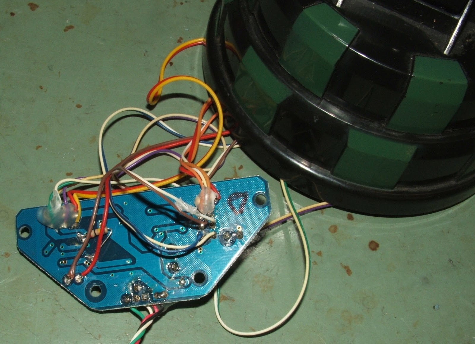
BTW the problem with the height motor not working is that the driver transistors only deliver about 3.5 volts.  Use a 9 volt battery to run it up and down a few times and then reconnect it to the USB interface and it will work normally.

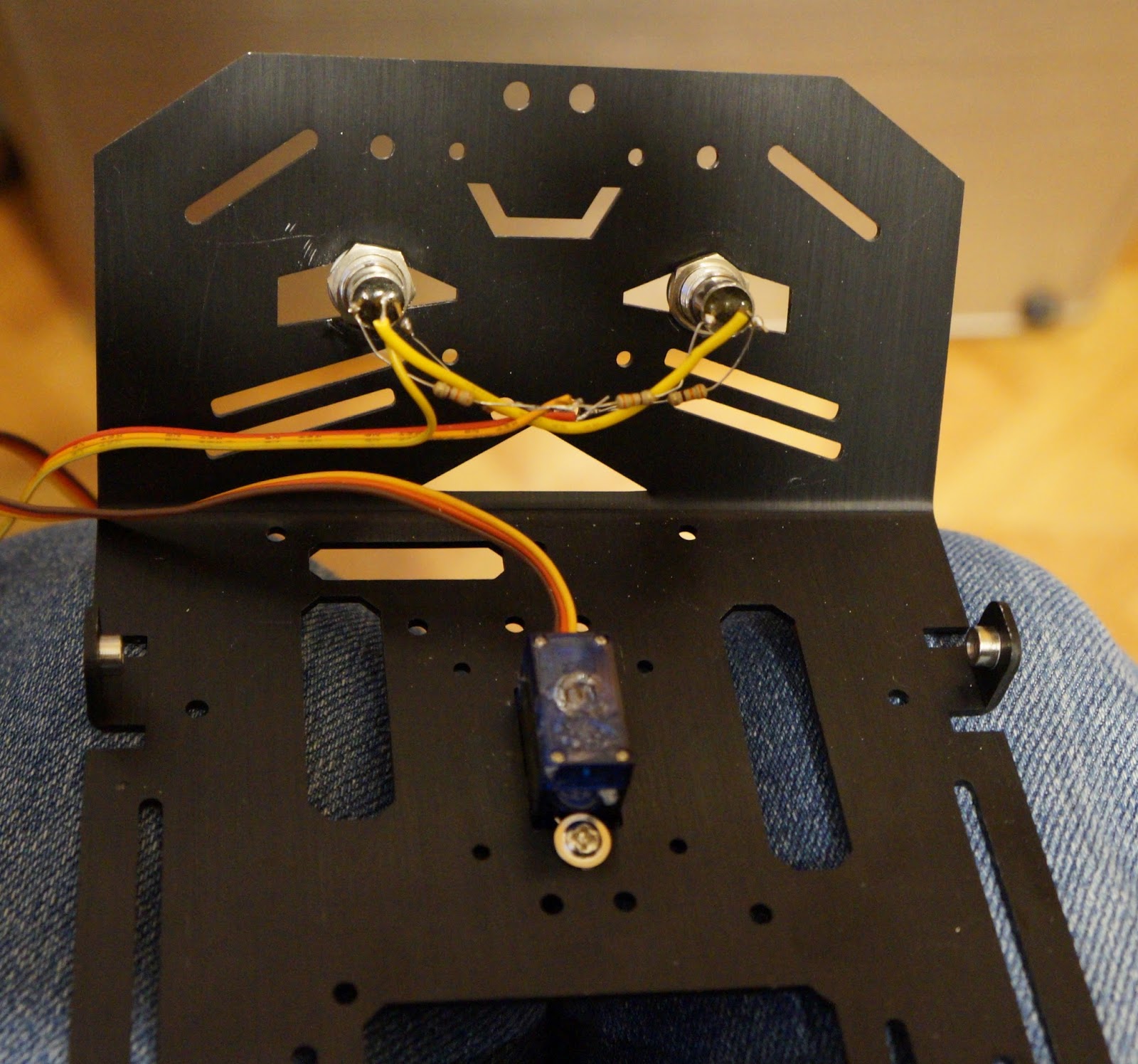
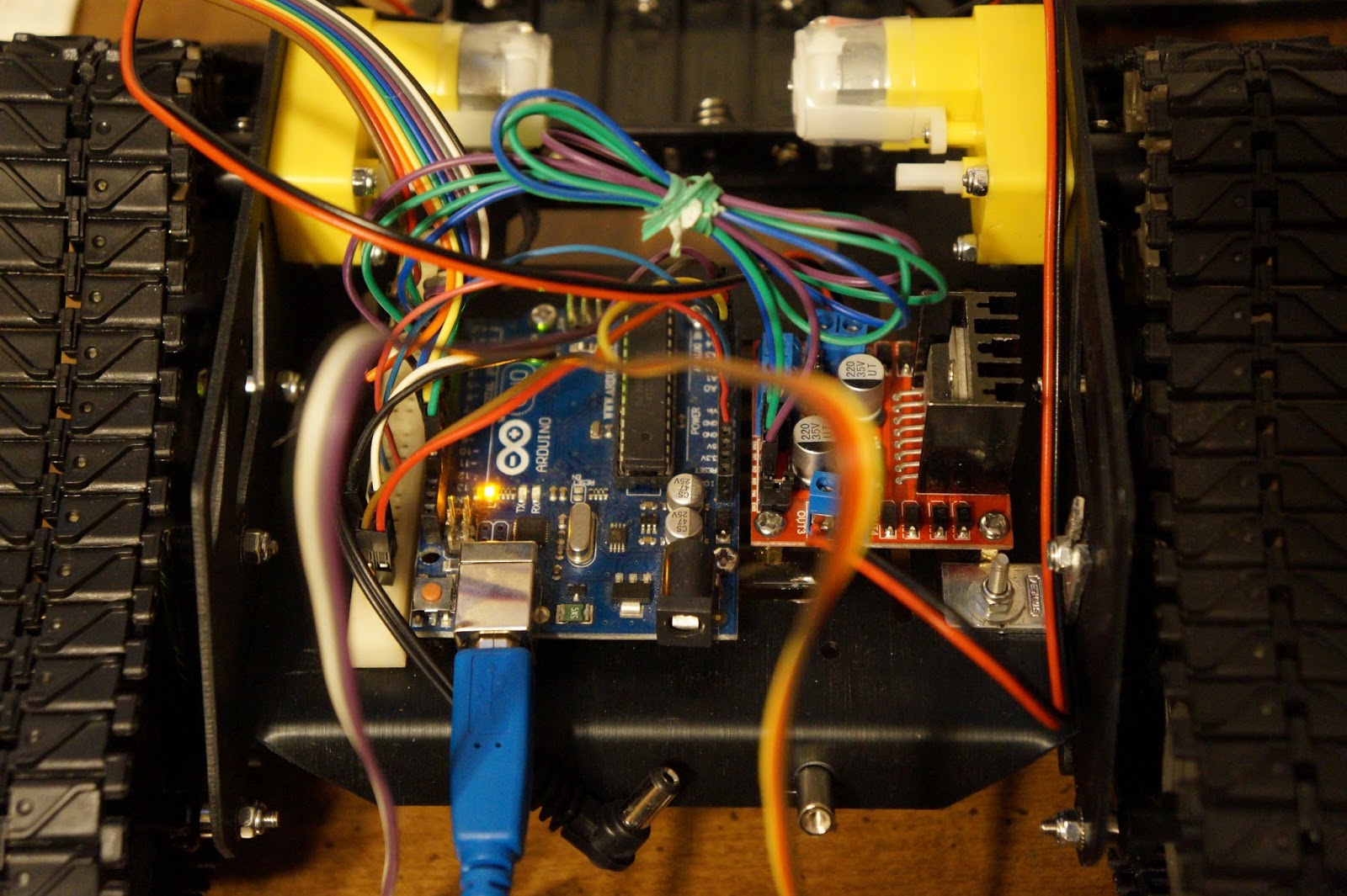
Next I will connect a motor controller and an Arduino to obtain working serial control of the launcher.  I used a L298 motor control for the turret and a TIP120 for the fire function.  The USB power was not sufficient for the fire motor so I used a 9V battery.  That was because of a problem with a broken gear and has been fixed.

Here is the first test video.  I need to get the right kind of missiles!

It is now attached to the Devastator tank, here is that video.

Here is a video of the tank with the three missile launcher attached.


Friday, March 9, 2018

Devastator Tank Mobile Robot Platform for Arduino or Raspberry Pi

I am building a "Devastator Tank Mobile Robot Platform" kit from dfrobot.  I bought it through robotshop_inc on eBay.  The hardware took only one hour to assemble.  The manual has lots of pictures to make assembling it easy.  Each type of screw has a bag with its part number on it.  The only tool I wish I had is the tiny wrench for the lock nuts.  You can use needle nose pliers but a wrench would be much easier to use.


Now for the electronics.  I don't have a schematic yet but here is what the wiring looks like so far.  I am using dual color LEDs for the headlights.  Three color LED's would be better as they can do white as well as colors like red for stop.

I am using a L298 motor controller.  To the left of the Arduino there is the power strip off a small breadboard to connect all of the power and grounds together.  Not visible in the back there is a two line LCD and in the front there is an ultrasonic distance detector.


Here is the first video of it running.

Here is a second video with headlights and servo.  Next to get a Nerf launcher on there.


Friday, March 2, 2018

Arduino UNO Running 12 WS2812 LED Strips with a BIGGER Font

I have modified my LED sign setup once again.  I now have an Arduino UNO Running 12 WS2812 LED Strips with a BIGGER Font.  The 12x8 font had to be typed in manually as I could not find one that suited me.  To get 12 lines running from a UNO I used both the "B" and "D" ports or D0 to D11 data pins.  The uppercase fonts only use 10X8 as the lower two rows are for lower case letters that extend below the line.

This is what the sign looks like in multi-color mode.

Here is the Video:


I can also do graphics on the LED sign.  This is a picture of the logo that I uploaded as a BMP to the sign for display.  I was looking for something with lots of color and with a black background.  White backgrounds do not work very well as the white light blinds you!  To display graphics I had to write a routine to rotate the bytes from horizontal to vertical orientation.  Then I added an offset to make it scroll up.  I should mention that this is running in 8 data line mode, the right side loops back to the next 8 rows on the left side to get up to 16 lines to display.


This is the video on YouTube.


Here are a couple of still shots of the sign displaying graphics.